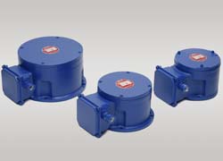
The Polyp Disc, owing to its braking capacity and its simple and rational system of assembly, can be employed in all industrial fields: it can in fact solve the following problems:
- BRAKING OF MOVABLE VERTICAL LOADS
winches - elevators - hoists - lifts - conveyors - inclined planes - roller shutters - shears - benders - cutting machines - lifting equipment in general. - BRAKING OF ROTATING PARTS OR PARTS WITH STRAIGHT-LINE MOTION
machine tools in general - presses - crane travelling and rotation - crabs - other travelling parts - BRAKING OF MOVABLE PARTS TO ENSURE A PRECISE, SAFE STOP AD BRAKING OF MACHINES IN GENERAL TO AVOID WORK ACCIDENTS TO THE OPERATOR
machine tools - rolling mills - draw-benches - packers building and tiling machines - weaving machines - paper factory machines - mixers - cement factory machines
OPERATION
By applying the current to the winding (6) the magnetic core (4) is activated and it attracts the mobile keeper (5). (5)
In this way, the pressure of the springs (7) on the disks is removed. The mobile disks (9), tooth mounted, can therefore turn, being moved by the hub which is splined to the brake shaft.
This, when the electric current is applied, the machine can operate in a normal condition.
As soon as the machine is disconnected (and therefore also the brake is disconnected), the magnetic flow ceases and the keeper, under the pressure of the springs, acts on the brake disks.
An immediate, soft and progressive braking is obtained and the rotating shaft stopped.
In case of any tension failure, the machine, to which the brake is connected, is automatically and safety stopped.
TECHNICAL CHARACTERISTICS
The Polyp Disc brake differs from any other similar brake on the market for the following main features:
- It can operate with three-phase alternate current without intervention of any auxiliary feeding equipment.
- It can be prearranged for running at any voltage by only modifying its windings
- It allows star-delta connection, therefore with possibility of obtaining two voltages feeding.
- Its very simple construction makes it well suitable to any machine braking.
- It has no linkages and devices at all, so that max. safety of operation is secured
- Soft braking, uniform and immediate at the same time
- Easy access for the adjustment of the braking moment as well as for adjustment of consumption

| TIPO | Grandezza | M massima coppia teorica (daNm) |
E energia dissipabile in 1 min (daNm) |
Gd² Momento dinamico (daNm²) |
dimensioni ingombro (1) (mm) |
Peso (Kg) |
|||||||||||
| P | N (H7) |
M | D max (2) |
E | F | G (H7) |
O | L | S | Q | W | ||||||
| PY 0 | A | 0,3 | 300 | 0,001 | 160 | 110 | 145 | 20 | 35 | 70 | 30 |
7 (3) |
125 | 11 | 3,5 | 115 | 9 |
| B | 0,5 | 500 | 0,002 | 9,25 | |||||||||||||
| C | 0,8 | 800 | 0,003 | 9,5 | |||||||||||||
| PY 1 | A | 1 | 1000 | 0,005 | 200 | 130 | 185 | 30 | 35 | 60 | 38 | 9 | 125 | 8 | 3,5 | 130 | 11,5 |
| B | 2 | 2000 | 0,010 | 11,9 | |||||||||||||
| C | 3 | 3000 | 0,015 | 12,3 | |||||||||||||
| PY 2 | A | 5 | 4000 | 0,02 | 250 | 180 | 230 | 40 | 50 | 65 | 54 | 11 | 140 | 10 | 4 | 155 | 20,1 |
| B | 8 | 5000 | 0,04 | 21,4 | |||||||||||||
| C | 12 | 6000 | 0,06 | 22,7 | |||||||||||||
| PY 3 | A | 16 | 8000 | 0,1 | 300 | 230 | 280 | 50 | 65 | 90 | 75 | 13 | 190 | 12 | 4 | 185 | 42,4 |
| B | 25 | 10000 | 0,15 | 44,8 | |||||||||||||
| C | 32 | 12000 | 0,20 | 47,2 | |||||||||||||
| PY 4 | C solo su commessa |
63 | 25000 | 0,40 | 350 | 230 | 325 | 60 | 80 | 100 | 128 | 17 | 210 | 12 | 4 | 210 | 70,2 |
1. Le quote non sono impegnative
2. I mozzi sono forniti con i fori sgrossati (rispettivamente Ø 10/14/20/25/25)
3. Il freno PY0 è dotato di tre fori a 120°
– Protezione meccanica IP44 (a richiesta IP55)
– Servizio S3 (int.40% – 360man/h) – A richiesta servizio S1 (magnete sempre inserito)
– Isolamento: classe F
– Per montaggio con asse verticale interpellateci
– Per velocità oltre 1800 g/min consigliamo l’adozione di dischi speciali
– A richiesta possiamo fornire freni per funzionamento in corrente continua

